|
|
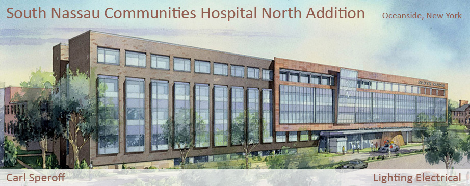
Building Statistics - Part 2 |
|
|
|
| Construction |
|
Construction of the North Addition of the South Nassau Communities Hospital began in December 2003 and was completed in May 2005. The construction manager on the project was Bovis Lend Lease. The project delivery method was guaranteed maximum price, and the actual construction cost of the project was $64,100,000. |
|
| Electrical |
|
Power is distributed at 5 kV to the existing hospital by the Village of Rockville Centre. The North Addition is served by a 5kV switch via an underground duct bank that is connected to new 5kV switchgear located on the corner of Oceanside Road and Oswald Court. The new switchgear is rated at 2,000 kVA, 5 kV, 3Ph, 5W primary and 480Y/277V, 3Ph, 4W secondary. Designed to provide the reliability and flexibility required in hospitals, the secondary power distribution consists of 480V, 3PH, 4W which provides service to lighting and equipment loads and is transformed down to 208Y/120V, 3Ph, 4W when necessary to provide power to receptacles and other equipment. A new 900 kW pad-mounted 480Y/277V diesel powered emergency generator was added to distribute emergency power for the new addition. As required by code, the secondary distribution system is separated into the following branches: |
Normal: |
|
Provides normal power to a majority of the facility loads that are not essential to hospital functions. Loads include general lighting, receptacle loads, and miscellaneous equipment. |
Life Safety: |
|
Provides continuous power via normal power or emergency generator for lighting and communications equipment related to the safety of building occupants. Loads include egress illumination, fire alarm systems, and paging systems. |
Critical: |
|
Provides continuous power via normal power or emergency generator for areas and equipment of the hospital essential to patient care. Loads include lighting, nurse call systems, and certain receptacles in areas such as nurse’s stations and medicine preparation areas. |
Essential Equipment: |
|
Provides continuous power via normal power or emergency generator for critical patient care and hospital functions. Loads include sump pumps, surgical HVAC, and elevators. |
Fire Pump: |
|
Provides continuous power via normal power or emergency generator for a fire pump to ensure water pressure. |
|
|
| Lighting |
|
In general, the lighting design was guided by the desire to provide high quality light that enhances architectural features, improves occupant safety, and conserves energy. Recessed and pendant mounted linear fluorescent fixtures are used throughout the space in conjunction with compact fluorescent and metal halide downlights. Halogen downlights are also used primarily as accent lighting in select spaces. Special high color rendering lamps are used in special areas such as critical care. In spaces such as offices and storage areas, occupancy sensors provide energy efficient controls. Daylighting is utilized in the lobby, conservatory, offices, and patient rooms. Spaces were designed to meet IESNA recommended illuminance levels and code requirements. |
| |
| Mechanical |
|
An existing boiler plant consisting of three 8500 lb/hr and one 20,000 lb/hr high pressure steam dual fired boilers provides heating for the existing hospital and the North Addition. A new 750 ton centrifugal chiller handles the cooling loads for the building. The building utilizes a variable air volume system. A total of seven air handling units provide heating, cooling, and ventilation to the new building. AHU-1 and AHU-2, with a capacity of 24,600 cfm each, serve levels 1 through 4 of the east wing. Levels 1 through 4 of the west wing are served by AHU-3 and AHU-4, each with a capacity of 19,800 cfm. Humidification steam from the existing plant feeds dispersion grids located in the each air handling unit. HVAC equipment is equipped with direct digital controls and is integrated into a central workstation. |
| |
| Structure |
|
The primary structure of the North Addition is supported by spread footings with grade beams. A 5” slab on grade reinforced with steel fibers sits on top of 6” of crushed stone and makes up the ground floor. Steel framing with a W18x40 typical beam size supports a floor system composed of a composite slab using lightweight concrete on top of a 20-gage 2” galvanized metal deck. A 1½“ deep wide rib steel roof deck spans between steel beams and supports roof and snow loads. Lateral forces are supported by braced and moment framing. |
| |
| Fire Protection |
|
The fire alarm system is a based upon a LAN hardware package that utilizes a solid state, microprocessor-based, analog/addressable monitoring and control system. The system employs peer-to-peer token ring network topology over common bus data communication lines between field processing units and network display units. The system includes a central processor unit, annunciator panels, field processing units, firefighter’s emergency telephone communications, peripheral detection, smoke and heat detectors, speakers, and manual pull stations. The fire alarm system is tied into the main fire alarm panel located in the existing panel. |
| |
| Transportation |
|
Three hydraulic powered passenger elevators and two service elevators provide access to all floors of the new addition. All elevators have a rated load of 4500 pounds and have a rated speed of 125 feet per minute. There are a total of three stairwells that serve each floor of the building. One is adjacent to the elevator lobby opposite the elevator shaft. There is also one stairwell at either end of the building. |
| |
| Communication Systems |
|
The telecommunications system was extended from the existing hospital into the new addition and runs back to the main telecom / computer room in the existing hospital. Voice and data closets house telecom copper, fiber optic, and coax patch panels. The nurse call system provides communication between master stations and sub stations via audio and or visual signaling. A code blue system provides audible and visual alarms via dome lights at the nurse call master stations within each departments as well as the hospital’s telephone switchboard room where an operator can provide assistance. A code blue emergency button is located at each critical care patient bed. |
| |
|
| |
All images provided courtesy of Cannon Design. |
|
|
|